How an Alemnis Standard Assembly Enhances Tribology Testing
Tribology stands at the intersection of science and engineering. It covers the intricate study of friction, wear, and lubrication, profoundly influencing the performance and longevity of mechanical components. Laboratories dedicated to tribology testing delve deep, extracting pivotal data on friction, lubrication, wear, and surface interactions, thereby shedding light on the failure mechanisms of these components. Given the empirical nature of tribology research, influenced by a myriad of parameters, it’s no surprise that comprehensive testing methods, from field tests to model tests, are employed. As we strive to optimize system performance and reduce maintenance costs, understanding these tribological characteristics becomes paramount.
Read more: How an Alemnis Standard Assembly Enhances Tribology TestingEnter the Alemnis Standard Assembly (ASA) – a groundbreaking tool set to redefine the paradigms of tribology testing. Dive in to discover how the ASA is revolutionizing this critical domain.
Versatility in Application
The ASA’s design allows for adaptability in various testing configurations. Whether it’s scratch testing, pin-on-disk testing, or investigating the friction force between two dissimilar materials, the ASA can be tailored to suit the specific requirements of the application. Such versatility ensures that researchers and technicians can optimize the device for their unique testing needs, enhancing the depth and breadth of their investigations.
Automated Precision and Ultra-High Strain Rates
Automation is at the heart of the ASA, making it a fully automated test platform that zeroes in on the mechanical properties of highly localized areas. This precision is further augmented by the ASA’s ability to achieve ultra-high strain rates up to 10,000 s-1. Covering a staggering 8 orders of magnitude, this feature allows for a comprehensive understanding of materials under various dynamic conditions.
Deformation Mechanisms Unveiled
The ASA’s prowess doesn’t end with mere testing. It also delves into the deformation mechanisms of materials. By integrating micro- and nano CT solutions, the ASA offers a unique perspective into how materials deform. Such insights are invaluable, especially when studying materials like polymers coatings, which have complex deformation patterns. Moreover, the acoustic emission data gathered during testing can shed light on the intricate processes occurring within the material.
The Future of Tribology Testing with ASA
In the ever-evolving field of tribology testing, the Alemnis Standard Assembly stands out as a beacon of innovation. Its ability to test fragile materials without damage, its adaptability to various testing methods, and its insights into deformation mechanisms make it an indispensable tool for researchers and technicians alike.
At Alemnis, we are proud to be at the forefront of this revolution. We invite you to explore the myriad possibilities the ASA offers and join us in shaping the future of tribology testing.
How to couple electron backscatter diffraction with micromechanical testing?
For materials scientists and researchers, understanding the intricate relationship between a material’s microstructure and its mechanical properties is paramount. Electron backscatter diffraction (EBSD) offers a window into the crystallographic orientation of materials, while micromechanical testing provides insights into their mechanical behavior. Combined, these techniques can reveal a wealth of information about deformation mechanisms, damage initiation, and overall material performance.
Step-by-Step Process to Couple EBSD with Micromechanical Testing
1. Sample Preparation: The Foundation of Accurate Results
The first step in this methodical approach is preparing the sample for both EBSD and micromechanical testing. Achieving a mirror finish through polishing is essential for EBSD, as it ensures accurate data collection. Additionally, etching the sample will reveal its microstructure, allowing for clearer analysis. For micromechanical testing, the sample should be meticulously cut and shaped to the desired geometry, ensuring that it fits the testing apparatus and provides reliable results.
2. EBSD Analysis: Deciphering Crystallographic Orientation
Once the sample is prepared, it’s time to perform the EBSD analysis. This technique determines the crystallographic orientation of the material, a crucial piece of information for materials scientists. By understanding this orientation, professionals can predict and identify the deformation mechanisms that might occur during subsequent micromechanical tests.
3. Micromechanical Testing: Probing Mechanical Behavior
With the EBSD data in hand, researchers can proceed with micromechanical testing. Techniques such as nanoindentation, microcompression, or microtensile testing are employed to study the material’s deformation and fracture behavior. One of the significant advantages of coupling these techniques is the ability to observe material behavior in real-time using EBSD, providing a dynamic view of the deformation processes.
4. Data Analysis: Correlating Microstructure with Mechanical Properties
The final step involves a thorough analysis of the results. By correlating the EBSD data with observations from micromechanical testing, researchers can draw connections between the material’s crystallographic orientation and its mechanical behavior. This correlation offers invaluable insights into the microstructure and mechanical properties of materials at the microscale, enhancing the depth and breadth of understanding for materials scientists.
The Role of Alemnis in Advancing Micromechanical Testing
Alemnis AG stands at the forefront of micro- and nanomechanical property measurement. With a suite of instruments designed for in-situ material testing, we are committed to advancing the field and providing tools that enable researchers to delve deeper into the intricacies of material behavior. By offering solutions that facilitate the coupling of EBSD with micromechanical testing, we play a pivotal role in the ongoing exploration of materials at the micro and nano scales.
In the ever-evolving field of materials science, the coupling of electron backscatter diffraction with micromechanical testing represents a significant leap forward. By enabling more comprehensive characterization of materials, this combination paves the way for breakthroughs in understanding deformation processes and material performance.
At Alemnis, we recognize the potential of this synergy and invite researchers and professionals to explore our range of instruments.
What is Stress Relaxation of Materials?
Understanding stress relaxation is essential for ensuring the long-term integrity and reliability of various materials under different conditions and is crucial for those designing structural applications. In this blog post, we look at the concept of stress relaxation, its occurrence in viscoelastic materials, and its importance in the design and application of materials.
Stress Relaxation: Definition and Phenomenon
Stress relaxation is the gradual reduction in stress over time while maintaining a constant strain. It is commonly observed in viscoelastic materials, particularly polymers, which show time-dependent relaxation when subjected to stress or strain. When a stress relaxation experiment is conducted, a sample is rapidly strained to a fixed length at a constant temperature, and the stress is recorded as a function of time. During the experiment, the length of the sample remains constant, allowing stress relaxation to occur at a molecular level through molecular relaxation and viscous flow.
Stress Relaxation vs. Creep
It is important to differentiate stress relaxation from creep, as they are distinct phenomena. Creep involves the constant application of stress while adding an increasing amount of strain. Creep experiments are conducted by subjecting a material to a constant stress and recording the resulting strain over time. In contrast, stress relaxation experiments involve applying a constant strain and monitoring the stress response over time. These differing experimental setups highlight the unique characteristics of stress relaxation and creep in materials.
Factors Influencing Stress Relaxation
Various factors influence the rate of stress relaxation in polymers, including the type of polymer, the presence of fillers, strain levels, strain rates, and temperature. Additionally, the polymer’s stress relaxation behavior can be significantly impacted by the nature and composition of the polymer.
It’s also important to know that the stress relaxation rate depends on the strain levels and strain rates applied to the material. Higher strain levels and faster strain rates typically lead to more rapid stress relaxation. Temperature also plays a vital role in stress relaxation, as higher temperatures generally result in faster relaxation.
Furthermore, external factors alone do not determine stress relaxation as it is also influenced by the intrinsic properties of the material. This includes its alloy, temper, and orientation. Considering these factors is crucial in accurately predicting and designing materials for specific applications.
Importance of Stress Relaxation in Design and Applications
Understanding stress relaxation is paramount when designing and selecting materials for structural applications because prolonged exposure to stress can result in irreversible deformation in plastic materials, compromising their structural integrity.
The data obtained from stress relaxation testing is particularly valuable in failure analysis and predicting material behavior under specific loading conditions. By accounting for stress relaxation, engineers can accurately model and simulate the long-term performance of materials, improving the overall reliability and safety of structural components.
Alemnis: Stress Relaxation Measurement Solutions
As scientific experts, it is essential to recognize the significance of stress relaxation and its implications in various industries. At Alemnis, we are dedicated to providing leading micro- and nanomechanical property measurement instruments in a range of material science applications.
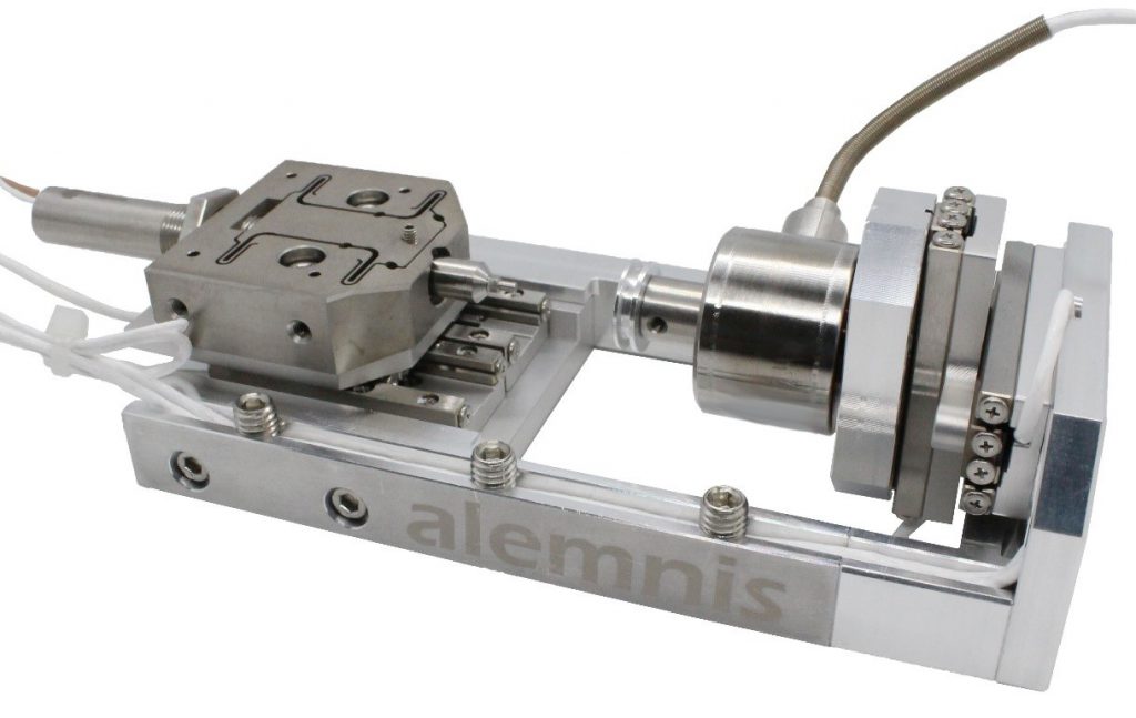
Our Alemnis Standard Assembly (ASA) is a unique and powerful solution used reliably for stress relaxation measurements. It can be used in in-situ, ex-situ, in synchrotron, and Micro CT configurations in true displacement mode for understanding compression artifacts, load drops, strain rate jumps, and sudden load excursions in real-time.
To ensure your stress relaxation measurements are accurate and reliable, contact Alemnis today, and let us show you the solution.

Fatigue vs. Creep Testing: What’s the Difference?
Creep testing and fatigue testing are two highly regarded methods used to assess the behavior of materials under varying loading conditions. Creep testing measures the gradual rate of deformation of a material under constant load and temperature conditions. Fatigue testing, on the other hand, involves subjecting a material or structure to cyclic loading. Experts must understand how these two methods are different, as they are necessary for evaluating the long-term performance and reliability of materials in various industries. In this blog post, we will look into the differences between fatigue testing and creep testing, including their underlying principles, testing procedures, and failure mechanisms.
Fatigue Testing
Fatigue testing is a method of mechanical testing conducted by adding cyclic loading to a structure. This method generates data on fatigue life and cracks, identifies critical areas, and assesses the safety of structures prone to fatigue. Fatigue occurs when a material undergoes fluctuating stresses and strains, eventually leading to cracks or a complete fracture. Fatigue tests aim to simulate real-world conditions and predict the material’s endurance under repetitive loading cycles. This method is common in the transport industry for testing components manufactured for automobiles and aircraft, as well as in the medical industry for testing implant materials.
Creep Testing
Creep testing assesses the progressive deformation of a material under constant load and temperature conditions. Creep is the tendency of materials to deform when subjected to long-term stress, especially at elevated temperatures. To perform a creep test, a constant stress is applied while maintaining a constant temperature. The corresponding strain is then recorded over time. Creep testing is crucial for understanding material behavior in high-temperature applications like jet engines and power plants.
Distinguishing Factors
The primary difference between fatigue and creep testing lies in the type of loading and the failure mechanisms involved. Fatigue testing looks at cyclic loading and how cracks or fractures are likely to develop due to fluctuating stresses and strains. In contrast, creep testing focuses on the material’s deformation under constant load and temperature conditions over extended periods. While both methods assess material performance, they address different aspects of long-term durability and reliability.
What is Creep Fatigue?
The term ‘creep fatigue’ often appears when discussing fatigue or creep testing. Creep fatigue, which involves crack elongation over time, may occur when materials are subjected to stress and extreme temperatures. It is important to note that surface finish and heat treatment factors can significantly impact fatigue life.
How is Creep Fatigue Tested?
To test for metal creep or fatigue, specialized procedures are employed. However, the earliest stages of creep are not visible to the naked eye and occur on a molecular level. Creep-to-fail testing is the most reliable method to determine the long-term performance of products with metal components. Different testing techniques can be utilized, such as flexural and compression creep tests. One commonly employed method is the tensile creep test.
Fatigue testing and creep testing serve different purposes in evaluating material behavior under specific loading conditions. While fatigue testing focuses on cyclic loading and crack propagation, creep testing assesses the deformation of materials under constant load and temperature conditions. Both testing methods are indispensable for comprehending the long-term performance and reliability of materials in diverse applications. By employing appropriate testing techniques, manufacturers can ensure the integrity of their products and meet the demands of various industries.
Alemnis: Providing Mechanical Testing Instruments
Alemnis is a pioneering company that empowers groundbreaking academic research in material science through its state-of-the-art micro- and nanomechanical property measurement instruments. Our cutting-edge products are designed to meet the diverse testing needs of researchers in various environments.
Our flagship product, the Alemnis Standard Assembly (ASA), offers superior accuracy and flexibility for both in-situ and ex-situ nanomechanical testing. This system is an ideal solution for long-term creep experiments, such as for example for holding constant loads for several hours throughout X-ray diffraction studies due to its high stability.
Contact a member of Alemnis today to learn more about fatigue and creep testing.
How to Perform Scratch Resistance Tests
Scratch resistance tests are an integral part of quality control processes, playing a vital role in assessing the ability of coatings and materials to withstand everyday wear and abrasion. By subjecting these materials to controlled scratching using various test methods, these tests provide valuable insights into their resistance to scratches and the impact of external forces. In this blog post, we will delve into the different methods and steps involved in performing scratch resistance tests, ensuring accurate and reliable results.
What is a Scratch Test?
Scratch resistance tests involve subjecting a coating or material to controlled scratching using different test methods. The primary reason is to evaluate the material’s resistance to scratches and the effects of external forces, and these tests provide valuable insights into a material’s mechanical properties, such as adhesion, hardness, and wear resistance. Moreover, they help identify potential weaknesses and enable the development of more resilient coatings.
How is a Scratch Test Performed?
A few simple steps must be followed for scratch testing to be effective. Firstly, the sample surfaces must be visually inspected to ensure it is clean and free from contaminants, as any impurities or damages can impact the test results. Additionally, the sample should be representative of the material or coating under evaluation.
Equipment Needed
Once the sample is prepared, select the appropriate scratch tester based on the desired test method and the material to be tested. Then, the tester needs to be set up correctly. This involves installing the chosen indenter on the testing equipment and calibrating it. Proper calibration ensures accurate and reliable measurements during the test.
Scratch Test
The actual scratch test is performed by applying a constant force or progressively increasing the force on the indenter as it moves across the sample surface at a constant speed. This process is conducted until failure events happen, such as scratch tracks, which can be further analyzed to determine the material’s resistance to wear and abrasion.
To accurately assess the scratch resistance, experts must compare the results with reference measurements. Scratch testing is a comparative procedure that relies on benchmark data. By comparing the obtained results with those of similar materials or coatings, the relative scratch resistance of the sample can be determined.
Scratch Tests Parameters
Researchers can monitor different scratch parameters during the test, such as applied load, scratch length, and scratch speed, to further understand the material’s scratch resistance. This data helps determine the critical failure points and the material’s ability to withstand external forces.
Analyzing the Results
After the scratch test, the results need to be carefully examined. Using a high-resolution or scanning electron microscope, the scratch is observed to determine the force at which the first cracks formed or when the coating chipped off. Different damage patterns, such as fishbone-like cracks, moon-shaped damage, or large-area chipping, can provide valuable insights into the material’s behavior under stress.
In addition to the primary analysis, it may be necessary to evaluate additional parameters depending on the scratch tester being used. Some instruments can measure tangential force and acoustic emissions, and these parameters provide additional information about the material’s performance under stress, offering a more comprehensive understanding of its behavior.
Additional Considerations
It is important to note that various factors, including coating thickness, substrate mechanical properties, and test conditions, can influence scratch resistance tests. By following these steps and guidelines, scratch resistance tests can provide valuable insights into the durability and performance of coatings and materials. These tests enable manufacturers to make informed decisions, improve product quality, and develop more resilient coatings that meet the demands of real-world applications.
Scratch Resistance Tests with Alemnis
Alemnis provides leading micro-and nanomechanical property measurement instruments that support scientists in breakthrough academic research in materials science.
One of the key solutions we offer is the Alemnis Standard Assembly (ASA), a modular indentation platform for use in-situ, ex situ, in synchrotron, and with micro CT. The ASA can be used with any scanning electron microscope to test for creep, fracture toughness, stress relaxation, and scratch testing to support your advanced mechanical testing requirements.
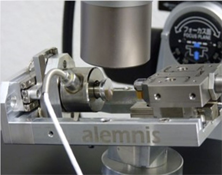
The ASA is most commonly used for scratch testing inside a scanning electron microscope, as it allows for real-time observation of the scratch and a deeper understanding of scratch deformation phenomena. The ASA can be used to perform scratch testing on coated sheets, paper, and hard coatings.
Contact Alemnis today to learn more about scratch resistance tests.
What are the Different Types of Tensile Gripper Systems?
From the intricate micro gripper to the robust hydraulic grips, tensile gripper systems are paramount to testing a material’s strength. Each type, with its inherent advantages and drawbacks, offers specific capabilities for testing various materials. In this article, we delve into the different types of tensile gripper systems and what makes each unique.
The Art and Science of Gripper Systems
Understanding the role of tensile grips in material testing requires an appreciation for the science behind the process. Microtensile testing is an approach to evaluating the strength of a material under tension. It differs from macroscale testing primarily in the volume of sample material required. A macro test for tensile strength will screen key mechanical properties (yield stress, elastic modulus, etc.) of bulk materials, whereas a microtensile test requires specially fabricated tensile samples with sub-millimetre geometries. Naturally, conventional gripper systems like manual vises, pneumatic grips, or hydraulic grips aren’t compatible with such tiny specimens.
Fabricating reproducible tensile samples at such small scales is an ongoing challenge – as is the issue of how to grip those samples during tensile testing. Microscale gripper systems have emerged as the ideal solution for grasping and manipulating microscale specimens in a range of fields. They can be purpose-built for specific applications, such as high-temperature tensile testing, where thermally-resistant diamond blanks can be cut to size and shape using focused ion beam (FIB) milling. Other applications are routine enough that grippers with a suitable gauge diameter range may be fit for purpose.
Gripping the sample solves part of the issue, but manipulating the sample to accommodate test conditions requires some form of compatible alignment system. Piezo-driven x- and y axes are typically used to position the samples below the grippers. Ideally, the gripper system will be combined with a precise rotation stage used to orient the sample.. A piezo actuator offers displacement from 20 – 100 µm in tensile direction.
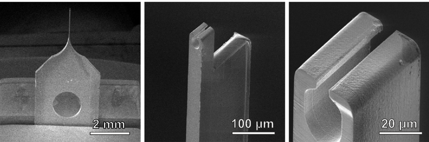
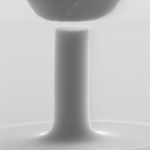
Alemnis Gripper Kit: Precision and Versatility
The Alemnis gripper kit is an innovative solution for tensile testing, allowing for meticulous tensile tests on mushroom-shaped pillars. The kit, equipped with an adapter to fit the gripper on the indenter and five standard grippers, is primed for precise application. Its silicon gripper, just 200 µm thick, is designed to grip samples with a gauge diameter of 1 – 15 µm and a mushroom diameter of up to 36 µm. Thanks to its meticulous design, it can accommodate misalignments up to 1° and 0.5 µm, keeping stress deviation within the sample below 10%.
Harnessing the Power of Customization
Flexibility defines the future of tensile gripper systems. As a testament to this, we offer additional grippers as separate items and field requests for customized grippers. This forward-thinking approach underscores the importance of tailoring gripper systems to meet specific needs, advancing the field of material testing.
Ready to Upgrade Your Testing Capabilities?
With a commitment to precision, versatility, and customization, we are poised to provide you with a solution that fits your specific needs. Choose from our range of standard or customized grippers and bring your material testing to the next level. Contact us today to learn more about how our gripper systems can revolutionize your testing process.
Using Nanoindenters to Determine Elastic Modulus
Nanoindentation is a ubiquitous analytical technique used to investigate a wide range of material properties. With increasingly compact geometries and high-resolution, nanoindenters can explore the mechanical properties of microscale samples to obtain results that are analogous to the macroscale, bulk material. The cost and convenience benefits of this are self-evident.
Nanoindenters can be leveraged in a choice of materials science test methods and applications. They are also increasingly pivotal in preliminary testing that enables further, more detailed mechanical analyses downstream.
Elastic modulus, for instance, is a key property underlying a range of dynamic behavioral mechanics including fracture toughness which is commonly calculated according to the Dukino and Swain equation. In brief, this considers fracture toughness a function of an applied indentation load, average crack length, the ratio of hardness to elastic modulus, and a geometric constant.
In this blog post, Alemnis will briefly explore how nanoindenters can be used to determine the elastic modulus of materials.
What is Elastic Modulus?
First, let us offer a short definition of elastic modulus. Often referred to as Young’s modulus, after British scientist Thomas Young, the elastic modulus of a material is a measure of its ability to resist bending or compressive forces and is consequently connected to both hardness and stiffness. Elastic moduli are determined as the ratio of tensile stress to strain within the material’s elastic limits for compressive and tensile loads; essentially comprising a measure of the force required to cause reversible (elastic) deformation.
Nanoindenters are used to probe materials and measure malleability/brittleness in relation to linear elasticity on a stress-strain graph. This is critical for gaining a thorough understanding of material performance under pre-defined use conditions and forecasting various dynamic deformation mechanics or modes of failure.
How Do Nanoindenters Determine Elastic Modulus?
To measure the elastic moduli of materials, nanoindenters bring a probe tip into contact with the surface at minuscule loads, typically just a few micronewtons (µN). This load is ramped up at user-defined rates to a maximum point and then decreased back down to zero at the same rate. Conventional indentation tests acquire load-displacement curves that are indicative of various mechanical properties. By observing the unloading curve, analysts can observe the elastic recovery of sample materials, which is a fundamental parameter in calculating elastic modulus.
Alemnis Nanoindenters
At Alemnis, we have developed a class-leading nanoindentation unit that pushes the frontiers of nanomechanical testing. The Alemnis Standard Assembly (ASA) exceeds traditional nanoindenters in terms of measurement accuracy and experiment flexibility. If you would like more information about measuring the elastic moduli of your materials with our innovative nanoindenter, simply contact a member of the team today.
Ultra-High Strain Rate Testing of Materials
The high strain rate behavior of materials is of enormous interest to product developers and the wider research community. Strain rate testing intersects an extremely wide range of market segments and is relevant to a variety of application areas, providing unique insights into how ceramics, electronics arrays, polymers, and so on, can withstand severe loading events.
At the macroscale, there are numerous proven methodologies for ultra-high strain rate testing (impact experiments, Kolsky pressure bar, etc.). However, the micro- and nanoscales remain comparatively unexplored due to the inherent limitations of the established testing methods. One of the foremost techniques used to explore the mechanical properties of sample materials is nanoindentation. Though incredibly valuable, nanoindentation tests typically employ quasi-static loading, which limits available strain rates to fairly low levels (<10-2s-1).
How to Achieve Ultra-High Strain Rates via Nanoindentation
The problem with high strain rate testing of materials via nanoindentation is that conventional micromechanical indenters with strain gage sensors, or load cells, have low resonant frequencies and poor sampling rates. This has the tandem effect of increased signal noise and low resolution due to slow feedback loops. Resolving load-displacement data at strain rates above 10-2s-1 requires a high data acquisition rate and extremely precise actuation frequencies. Only piezoelectric actuation and sensing offer that level of control for micromechanical testing.
Additionally, ultra-high strain rate testing via nanoindentation is facilitated by novel test methods like micropillar compression. Using a piezo-based nanoindenter and a microscale pillar of lithographically-generated or extracted sample material, it is possible to achieve strain rates up to 10,000 s-1. Owing to the sample’s extremely small dimensions relative to various test parameters (actuation velocity, inertia, wave travel time, etc.), fatigue, impact, and dynamic deformation phenomena can be acquired at ultra-high strain rates without interference.
Currently, fused silica micropillars exist as a proof of concept for how ultra-high strain rate testing can be carried out for numerous other materials with unexplored high-strain rate properties.
Read our full, in-depth article on Ultra-High Strain Rate Testing with a case study on fused silica micropillar compression for more details.
Ultra-High Strain Rate Testing with Alemnis
Alemnis specializes in micro- and nanoscale indentation testing for a wide range of materials, leveraging our pioneering Alemnis Standard Assembly (ASA) with proprietary high- and ultra-high strain rate modules. For strain rates of 1,000 s-1 and above
Alemnis offers four distinct configurations:
- VHS-1-1, for impact/fatigue testing at strain rates of up to 1,000 s-1 using a piezo stack actuator with a normal load range of 1N.
- UHS-1-1, for impact/fatigue testing at ultra-high strain rates of >1,000 s-1 using class-leading SmarTip actuation with a range of +/- 175V.
- UHS-1-3, for ultra-high strain rate tests with additional tri-axial sensing (normal and lateral force) with a lateral load range of +/- 0.1N.
- UHS-3-3, a complete ultra-high strain rate testing solution with tri-axial sensing and actuation enabling novel nanotribology applications.
If you would like more information about integrating the Alemnis ASA for your high strain rate testing objectives, simply contact a member of the sales team today.
In-Situ Mechanical Testing for Real-Time Materials Characterization
Observing how materials respond to applied stress in their native state is fundamental to understanding their mechanical properties (creep deformation, fracture toughness, hardness, elastic modulus, etc.). Limited insights can be gained from structural and surface analysis of samples before and after a mechanical load has been applied, typically via indentation. However, this fails to yield accurate data regarding the real-time deformation behavior of samples under test.
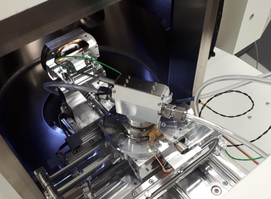
In situ mechanical testing is the only way to observe the real-time mechanical performance of samples under applied loads. For instance, conducting nanoindentation in a scanning electron microscope (SEM) environment allows researchers to visualize key parameters of their mechanical tests, including the actual deformation mechanics of samples in real-time.
Read More: What Properties Can Be Measured By Nanoindentation?
In this article, Alemnis briefly explores how real-time materials characterization can be actualized using vacuum-compatible nanoindenters and complementary SEM-based imaging.
In Situ Mechanical Testing: Challenges & Solutions
Indentation is a common mechanical testing method used to explore the physical properties of different sample types (alloys, ceramics, polymers, etc.). The basic principle involves the application of a mechanical load via a diamond probe tip to determine a sample’s resistance to deformation. Typically carried out ex-situ, various indentation methods have been used to investigate the elastic moduli and hardness scales of materials as a function of load-depth curves. However, conventional indentation is unsuitable for in situ mechanical testing.
Because surface observations are made after the fact, all conclusions drawn from load-depth data that pertain to specific deformation mechanics within the material are largely speculative. This complication is compounded by the rise of nanomechanical testing based on sub-micro scale (μm) indentation. In situ mechanical testing subsequently requires a powerful imaging tool that can offer nanoscale observations of sample mechanics in real-time.
With far superior spatial resolution than optical light-based microscopy, SEMs have significantly shifted the goalposts of modern materials characterization. Prior to the onset of SEM, researchers were limited to nominal magnification ranges of up to 1000x due to the limited resolving power of visible light. A focused electron beam offers magnifying capabilities of up to 50,000x which yields extremely high lateral resolution ranging down to just a few nanometres (nm). Yet the limited geometries and vacuum pressures of sample chambers make it impossible to couple SEM imagery with conventional nanoindenters.
Small-scale, vacuum compatible nanoindentation modules are subsequently a prerequisite for in situ mechanical testing. This can yield a range of valuable results, providing accurate data regarding crack propagation, delamination, fracture onset, and more.
Real-Time Materials Characterization with Alemnis
Alemnis offers a unique solution for in situ mechanical testing of myriad sample types with real-time imaging via SEM. The Alemnis Standard Assembly (ASA) is a small footprint nanoindenter comprising a piezo actuated displacement head with an integrated sensor for completely closed-loop indentation testing. This module can be mounted and operated within the sample chamber of an SEM with sufficient space, enabling researchers to observe the real-time displacement of their samples down to a single nanometre.
If you would like to learn more about the unique Almenis solution for nanoindentation testing, read our previous blog post: What is a Nanoindenter?
We also provide custom mounting solutions and modifications for SEM integration. Contact a member of the Alemnis team today to learn about costing an ASA configuration with your SEM unit.

What is a Nanoindenter?
A nanoindenter is a versatile instrument used to test the mechanical properties of materials. Primarily developed for localized hardness testing, nanoindentation is now widely used to measure creep, fracture toughness, elastic modulus, stress relaxation, cracking, di slocation nucleation, and the viscoelastic properties of samples.
In this blog post, Alemnis explores the working principles of nanonindenters in more detail.
Nanoindenter Working Principles
At the heart of a nanoindenter is a small probe loaded with a calibrated indenter tip, which may be pyramidal, flat, spherical, wedged, or some other shape. This is used to interrogate the surface of a material and measure the subsequent force-displacement data.
Conventional nanoindenters are typically load-controlled instruments where the tip is brought into contact with the surface under a pre-defined load. Once the nanoindenter has contacted the sample, the load is increased and the tip indents into the material. The area of contact between the tip and the sample, the applied force of the nanoindenter, and the depth of displacement are subsequently used to determine the material’s mechanical properties. The disadvantages of a load-controlled system become obvious when doing compression tests on small structures (e.g., micropillars, 3D structures, etc.) where the load feedback loop cannot cope with sudden displacement excursions. In such cases, nanoindentation measurements using displacement control are far superior.
Traditionally, the size and depth of the residual indentation imprint is taken to calculate the material hardness. This is characterized according to one of several indentation hardness scales, including the Vickers and Brinell scales. Nanoindenters have proven valuable for microhardness testing where samples are small or thin, and they have also demonstrated unique performance for measurements where the microstructural properties of a sample are complex or are non-homogenous.


Typical example of a nanoindentation load-depth curve (left) and corresponding residual indent (right)
Applications of Nanoindentation Testing
Nanoindenters are broadly used to test the properties of hard coatings and thin films. As the dimensions of engineering and electronic components continue to decrease, it is vital that local mechanical properties are tested with very little residual impressions. Conventional techniques are largely incapable of testing small-scale components non-destructively, and in best case scenarios may impact the material properties of miniaturized components. Nanoindentation is subsequently used to characterize a range of materials to assist in research and development of new products and solutions. In the case of coatings, a nanoindenter can test the properties of even very thin films (e.g., thickness < 1 µm) without any influence from the properties of the substrate underneath.
Increasingly, nanoindentation has been used to test the complex properties of more dynamic material types including soft, hard, inorganic, and organic samples.
The Alemnis system is fully compatible for in-situ scanning electron microscopy (SEM) experiments, and ex-situ testing with Synchrotron beamlines and standard optical microscopes. This provides new levels of flexibility for dynamic material testing under high strain rates ( up to 10’000 s-1 ) and over very wide temperature ranges (from -150°C up to 1000°C)
Example of micropillar compression experiment with a flat punch diamond indenter
Localized mechanical testing of materials using the Alemnis system can provide new ways of understanding product failure under end-use conditions. It can be used to measure very small volumes of a specific material which can be in the form of a micropillar fabricated by focused ion beam (FIB) milling or by lithographic techniques such as LIGA. Small volume testing can help to understand the fundamental deformation mechanisms and if performed in-situ allows direct observation of the resultant phenomena, e.g. twinning or slip in metals, stress relaxation in ceramics or creep of oxide structures.
This level of precision has also been explored in the world of emerging biomaterials, offering new understandings of how tissues behave at a cellular level and how this behaviour can be modified. Quantitatively measuring the mechanical properties of biomaterials could provide new insights into biological behaviours, supporting research into innovative pharmaceuticals and medical devices. The Alemnis system can be used to do ex-situ bio-testing in various environments, such as controlled relative humidity, temperature or in liquids (e.g., saline or body-mimicking fluid).
The Unique Alemnis Solution
Alemnis is a specialist in small-scale mechanical testing for materials science research, with a nanoindentation system which can be used in either compression or tension modes. This means that a pillar can be compressed with a flat punch, a surface can be indented with a sharp indenter, or a microscale dogbone sample can be tensile tested, all with the same system. Such high versatility is unmatched and based on years of combined experience.
Read More: What Properties Can Be Measured by Nanoindentation?
The Alemnis system features a true displacement mode as well as various ultra-high strain rate options which permit strain rate jump tests, fatigue testing and dynamic mechanical analysis (DMA). Coupled with the latest state-of-the-art electronics and environmental control, the Alemnis system offers more versatility than any other.
If you would like to learn more about our nanoindenter systems, please do not hesitate to contact us directly.