FATIGUE TESTING
Fatigue testing is the process of measuring the failure limit of a material when subjected to stress such as repeated axial loading or bending. Fatigue testing detects progressive localized permanent structural change occurring in a material subjected to conditions that produce fluctuating stresses and strains at some point or points and that may culminate in cracks or complete fracture after a sufficient number of fluctuations. Fatigue testing is commonly performed by axial loading or in bending, thus producing tensile and compressive stresses. The stress is usually cycled in some way, either in a constant manner or in increasing intensity until the failure limit is attained.
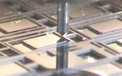
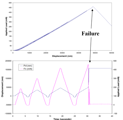
Indentation fatigue test on a MEMS beam using cyclic incremental loading until failure
The Alemnis Standard Assembly (ASA) can be used to perform standard nanoindentation fatigue tests (typically at low oscillation frequencies) or high frequency oscillatory fatigue tests with the Ultra High Strain (UHSR) option. The flexibility of the system allows fatigue testing to be performed in many sample orientations and configurations. Examples include quasi-static uniaxial indentation, high frequency indentation fatigue, beam bending, micropillar compression fatigue, impact fatigue, etc.
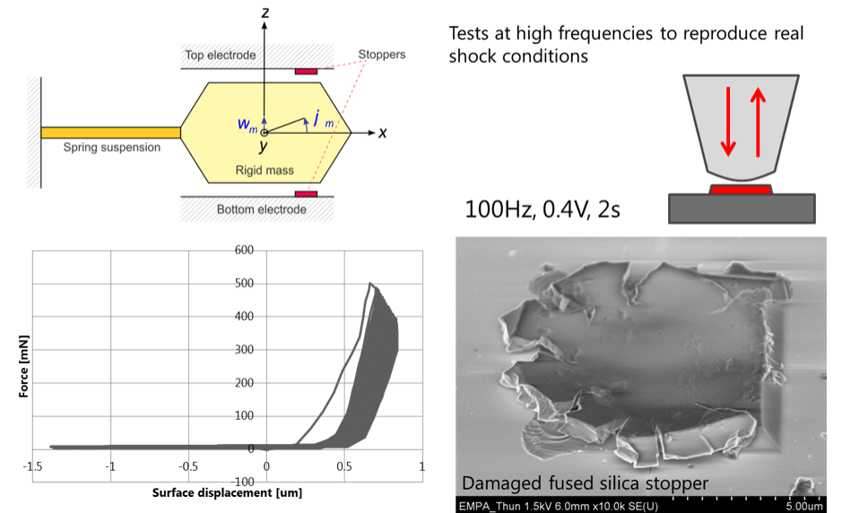
Simulation of a capacitive accelerometer stopper damaged by shock at high frequency